

VEHICLE APPLICATION
- YEAR: 2014 - 2019
- MAKE: Polaris
- MODEL: RZR XP 1000
- ENGINE: 1000cc
TOOLS REQUIRED
- 2.5mm, 4mm, 5mm Hex Key
- 1/2" Wrench/Socket
- 3/8" Deep Socket
- 5/16" Nut Driver
- T40 Torx Screwdriver
- Phillips Screwdriver, Flat Blade Screwdriver, Razor Blade, and Wire Cutters
Note: Approximate Install Time: 2 Hr 00 Mins.
BEFORE YOU START
• Please read the entire installation manual before proceeding.
• Ensure all components listed in the Bill of Materials are present.
• If you are missing any of the components, call our customer support at (909) 947-0015.
• Do not work on the vehicle while the engine is hot.
• Make sure the engine is turned off, the vehicle is in Park and the Parking Brake is set.
THREAD LOCKER USE
We have provided a small tube of thread locker in your kit. Whenever you see the symbol above on a step of the instructions, apply 1 small drop of the thread locker to the threads of the screws or bolts. This will keep your hardware from vibrating loose during rough driving. If the hardware ever needs to be removed, do so slowly to avoid having the inserts strip out from the plastic.
WARNING:
THIS EQUIPMENT SHOULD BE INSTALLED, ADJUSTED, AND SERVICED BY PERSONNEL FAMILIAR WITH THE CONSTRUCTION AND OPERATION OF THIS TYPE OF EQUIPMENT AND THE HAZARDS INVOLVED. FAILURE TO OBSERVE THIS PRECAUTION COULD RESULT IN SEVERE INJURY. READ THIS MANUAL THOROUGHLY AND MAKE SURE YOU UNDERSTAND THE PROCEDURES BEFORE YOU ATTEMPT TO OPERATE THIS EQUIPMENT. THE PURPOSE OF THIS MANUAL IS TO PROVIDE YOU WITH INFORMATION NECESSARY TO SAFELY OPERATE, MAINTAIN, AND TROUBLESHOOT THIS EQUIPMENT. DO NOT USE THIS EQUIPMENT FOR ANY REASON OTHER THAN ITS INTENDED PURPOSE. FAILURE TO FOLLOW THESE INSTRUCTIONS WILL VOID ANY WARRANTY. KEEP THIS MANUAL FOR FUTURE REFERENCE. THE INFORMATION CONTAINED IN THIS MANUAL IS SUBJECT TO CHANGE WITHOUT NOTICE.
Product will intake and expel both air and loose materials with high force and velocity.
• Install the product on the roll cage, so air inlet is not blocked.
• Do not place face, hair, extremities, clothing, or other loose material in front of air inlet or outlet during use.
• Install product securely to roll cage and avoid placing hair, extremities, clothing, or other loose material in front of air inlet during use.
Moving parts are sharp and could cause personal injury.
• Keep fan safety guard and exhaust cover in place while operating and after service.
• Disconnect the product from the power source before servicing.
Scavenge Fan is designed for use in conjunction with an UTV’s operating manual, and state and federal law.
• Keep your seat belt fastened and wear a helmet while operating the vehicle.
Risk of electric shock!
• Improper installation, maintenance or operation could cause serious injury or property damage.
EXPLODED VIEW
PARTS LIST
INSTALLATION STEPS
BEFORE YOU BEGIN
This installation requires the use of a powered electrical busbar found underneath the hood of the vehicle. The provided Wire Harness (J) is designed to work with these factory-installed electrical posts on the busbar and has the length of wire necessary to power the Particle Separator's scavenge fan anywhere on the vehicle. If the busbar in your vehicle is not connected to the vehicle's battery do not begin the installation of the Particle Separator. You will need to install both a power and a ground cable from the vehicle's battery to the busbar. Although not required, Polaris offers a busbar harness kit with complete instructions about how to do this.
STEP 1
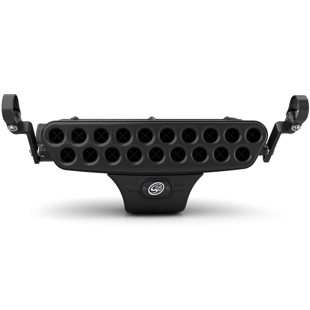
Based on the room you have available, and accommodating for other accessories, determine where you want to mount the Particle Separator Assembly (A) to your roll cage. Make sure you have enough room to fit the clamps and Particle Separator on the roll cage without any interference. Planning ahead will save you time and frustration during the installation. In these instructions, the Particle Separator Assembly (A) will be installed on the lower horizontal bar, highlighted in red.
STEP 2
Once the mounting location has been determined, install both Straps (O, HP1392-01) onto the roll cage. Loosely wrapping some plastic around the roll cage will help with sliding the straps onto the roll cage and prevent scratches.
STEP 2 (IMAGE 2)
STEP 3
Install the Pivot Body (N, HP1392-01) onto the Strap (O) with the supplied M8 Screw (S, HP1390-01), M8 Locknut (T, HP1390-01), and M8 Washers (Q, HP1390-01). Do this for both Straps (O). DO NOT tighten the M8 Screws (S) and M8 Locknuts (T), leave this connection hand-tight for now.
STEP 4 💧
Using a 4mm hex key, Install the Adapter (L, HP1392-01) onto the mounting bosses of the Particle Separator (A) with the supplied M6 Screws (P, HP1390-01) and M6 Washers (U, HP1390-01). Fully tighten these screws. Repeat this step on the other side of the Particle Separator Assembly (A).
STEP 5 💧
Determine the proper angle to mount the L-Bracket (M) based on the desired location for the Particle Separator (A). Once decided, using a 5mm hex key, secure the L-Bracket (M, HP1392-01) to the Adapter (F) with the supplied M8 Screw (R, HP1390-01) and M8 Washer (Q, HP1390-01).
Before tightening the M8 Screw (R), make sure the L Bracket is properly seated in the adapter. If the ribs in the L-Bracket (M) are not properly seated inside the grooves of the Adapter (F) damage to these parts may occur. Do not attempt to rotate these parts once assembled, they are designed to lock into place once the M8 Screw (R) is tightened down.
Repeat this step on the other side of the Particle Separator Assembly (A). Double-check that both L-Brackets (M) are pointed in the same direction and are aligned with each other.
STEP 5 (IMAGE 2) 💧
STEP 6 💧
Using a 5mm hex key, install the Particle Separator Assembly (A) onto the roll cage by securing the L-Bracket (M) to the Pivot Body (N) using an M8 Screw (R, HP1390-01) and M8 Washer (Q, HP1390-01). Repeat this step for the other side of the Particle Separator Assembly (A). Having an extra pair of hands to hold the Particle Separator Assembly (A) to help line up the holes will make this step much easier.
STEP 7
Once you are satisfied with the position of the Particle Separator Assembly (A), using a 4mm hex key and a 1/2" wrench/socket, fully tighten the M8 Screw (S), M8 Locknut (T), and M8 Washers (D) to lock the Strap (O) into place on the roll cage. Repeat this step for the other clamp assembly.
STEP 8
Double-check that all screws and locknuts are fully tightened down and that the Particle Separator Assembly (A) is firmly attached to the roll cage.
STEP 9
Loosen the screw that is securing the passenger side Frogzskin side cover to the vehicle. Then, lift up and pull towards the front of the vehicle to remove the Frogzskin side cover.
STEP 9 (IMAGE 2)
STEP 10
Place a #56 Hose Clamp (G, HP1359-00) over the stock airbox inlet, insert the smaller end of the Duct Adapter (F, HP1359-00) into the stock airbox inlet, then tighten the hose clamp with a 5/16” nut driver to secure the Duct Adapter (F) to the stock airbox inlet.
STEP 11
Insert one end of the Flexible Duct (E) onto the Duct Adapter (F). Bring the other end towards the outlet of the Particle Separator Assembly (A). If you have any excess length of the Flexible Duct (E), make a mark of where you need to cut. Provide enough length of Flexible Duct (E) so that it can easily reach from the outlet of the Particle Separator Assembly (A) to the stock airbox inlet without it becoming taught.
STEP 12
Using a razor blade, pierce the Flexible Duct (E). We suggest making the pierce equidistant between the wire reinforcement. While keeping the razor blade centered between the wire reinforcement, begin making your cut and continue until you complete one loop around the Flexible Duct (E).
STEP 13
Once your razor blade cut has looped around the Flexible Duct (E) one complete rotation, use scissors or a razor blade to cut inward towards the wire reinforcement. Do not try to cut through the wire with scissors or a razor blade, use a mini-bolt cutter or a heavy-duty wire cutter to finish cutting through the wire reinforcement.
STEP 14
Install End Cuffs (V, HP1359-00) and #56 Hose Clamps (G, HP1359-00) onto both ends of the Flexible Duct (E).
STEP 15
Install the End Cuff (V) and Flexible Duct (E) onto the Duct Adapter (F), then tighten the #56 Hose Clamp (G) with a 5/16” nut driver.
STEP 16
Insert the other end of the Flexible Duct (E) onto the outlet of the Particle Separator Assembly (A), then tighten the #56 Hose Clamp (G) with a 5/16” nut driver.
STEP 17
Install the Side Cover (B) onto the vehicle by inserting the mounting tab into the body panel (towards the rear of the vehicle), followed by maneuvering/rotating the Side Cover (B) into the correct position. Then, using a 4mm hex key, secure the Side Cover (B) to the vehicle with a supplied M6 Screw (C, HP1363-00) and M6 Washer (D, HP1363-00).
STEP 17 (IMAGE 2)
STEP 18
Use the provided Velcro Strap (H, HP1359-00) to secure the Flexible Duct (E) to the roll cage.
STEP 19
Familiarize yourself with the Wire Harness (J, HP1394-01) and each of the components. The Wire Harness (J) contains an electrical relay, a fan connector, and a set of three-ring terminals. In the coming steps the set of ring terminals will be attached to the vehicle’s electrical busbar and the fan connector will connect to the scavenge fan in the Particle Separator Assembly (A).
STEP 20
Remove the vehicle’s hood by rotating the locking tabs then pulling the hood towards the front of the vehicle.
STEP 20 (IMAGE 2)
STEP 21
Using a 3/8” long socket, remove the three lock nuts from the vehicle’s electrical busbar, then attach the set of three-ring terminals, from the Wire Harness (J) to the matching busbar posts. Once the ring terminals have been placed on the correct busbar posts, reinstall the three locknuts to the busbar posts.
STEP 22
Run the fan connector through the rubber grommet to the inside of the vehicle. This wire will be coming through the wall behind the dash. Pull the entire length of the fan connector wiring through the grommet, this length of wire will be needed to reach the scavenge fan in the Particle Separator Assembly (A).
STEP 23
You are free to route the fan connector to the Particle Separator Assembly (A) however it is most convenient for you, however, we prefer to first run the wiring down the driver side wall, then to the back of the vehicle inside the driver side body panels (path shown in the image). This keeps the wiring out of sight and prevents it from becoming tangled with anything. By removing a few screws and/or plastic rivets around the door frame (shown in Image 2 and Image 3), the body panels can be opened up enough to run your wiring inside them.
Whichever direction you choose, complete the routing of the fan connector wiring all of the way to the Particle Separator Assembly (A) before proceeding to Step 24.
STEP 23 (IMAGE 2)
STEP 23 (IMAGE 3)
STEP 23B
The plastic rivets can be removed with a flat-head screwdriver, or panel popper, by unseating the locking tab then prying the entire rivet from the body panel.
STEP 23C
The screws can be removed with a T40 Torx Screwdriver.
STEP 24
Once you have finalized the path of the fan connector wiring to the Particle Separator Assembly (A), connect the fan connector to the scavenge fan.
STEP 25
Secure any excess wiring from the fan connector to the roll cage with Cable Ties (I, HP1394-01) or excess Velcro Strap (H), then go back to the hood compartment and secure the relay and excess wiring to the frame of the vehicle with supplied Cable Ties (I).
STEP 25 (IMAGE 2)
STEP 26
Reinstall the hood onto the vehicle. Slide the hood towards the back of the vehicle, then rotate the tabs to lock the hood into place.
STEP 27
Double-check that all connectors are plugged in and secure. Turn the ignition on and make sure air begins blowing out of the exhaust of the Particle Separator Assembly (A). If air is not blowing out, double-check your electrical connections. When you turn the ignition off, the fan will stay on for several seconds and is normal. Your installation is now complete!
SIDE NOTE
S&B recommends that you apply a layer of waterproof grease, such as made by Bel-Ray or Super Lube, on the inside flange of the stock air filter to keep dust from bypassing the seal.
ONGOING MAINTENANCE
Your Particle Separator requires very little if any maintenance depending on where you drive; however, you should check to make sure that none of the openings in front of the Particle Separators are blocked by mud or other debris each time you exit the UTV. You should also make sure the scavenge fan is operating properly. To do so, simply check to make sure the fan is still blowing out air (for about 15-20 seconds) when you turn off your UTV as this is a normal condition. If the fan is not blowing out air or the airflow seems lower than when you initially installed your system, please contact S&B tech support. To clean your Particle Separator, review the cleaning instructions below.